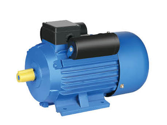
An electric motor converts electrical energy into mechanical energy by creating a force between opposing magnetic fields. Electricity is passed through a series of coils, magnets, and brushes to make the shaft spin. A commutator and brushes then make the current in the electromagnet turn and power other coils to generate more electricity. This process is repeated over and over to make the motor spin continuously. This type of motor is used in everything from cars to drills to industrial production machinery.
Motors can be powered by direct current (DC) from rectifiers or batteries, or they may be alternating current (AC) from the power grid or electrical generators. They can also be single-phase or three-phase, brushless or brushed, radial flux or axial. There are many different types of electric motors, each designed for a specific purpose.

The fundamental parts of an electric motor are the rotor, stator, and commutator. The rotor has metal bars and induction coils around it that make up the motor core. The commutator is a cylinder of multiple metal contact segments on the rotor. Two or more electrical contacts called brushes made of a soft conductive material like carbon press against each segment of the commutator as the rotor rotates, supplying current to the rotor windings. The commutator also periodically reverses the direction of current in the rotor windings to keep them from overheating.
A rotor can be made with either salient-pole or nonsalient-pole magnetic poles. Salient-pole rotors have projections on the core that create north or south poles when they are energized with electric current. In this configuration, the rotor has a wire winding that wraps around each pole, which then forms its magnetic field when current flows through it. Nonsalient-pole rotors have an evenly distributed field and can be either shaded or cage-wound.
Motors with salient-pole magnets are more efficient than those with nonsalient-pole magnets because they don’t waste energy reversing the polarity of the magnets. However, the motor requires intelligent controls to hit peak efficiency. This includes fast and accurate current control, a good understanding of the force-per-current of each phase arrangement, and logic that ties all this together with low latency.
To make an electric motor spin correctly, it needs to have a current that is proportional to its power and that equals the sum of its force-per-current values across all electrical angles. This is called the motor constant and it’s found using Equation 6.
To find out what that number should be, you need to know what current each phase is drawing during startup. This is measured as Locked-Rotor Amps (LRA), which happens instantly during start-up, and RLA – rated load amps, which is the current the motor should pull at all operating conditions. To get a precise value, you need to do some complicated math and use a motor-testing software application.


